
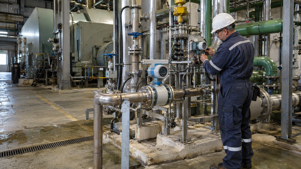
A generator stator cooling water system does not contain a large number of instruments, but the instruments it does contain are rarely unimportant.
The system must circulate clean, controlled water through or around current-carrying components while maintaining adequate heat removal. A small deterioration in flow, pressure, temperature or water quality can indicate blockage, leakage, pump degradation, cooler fouling or contamination. The instrument may be physically small, yet its signal can influence alarms, load limitations and decisions about whether the generating unit can remain in service.
This is why purchasing a replacement instrument from a short description such as “pressure transmitter for stator cooler outlet” is risky. The description may identify the location, but it does not reveal whether the original instrument measures gauge pressure, differential pressure or another process variable. Nor does it define the process connection, calibrated range, static-pressure limit, materials, output protocol or alarm function.
A reliable purchase begins by reconstructing the complete measurement duty.
Understand the cooling circuit before selecting the instrument
Generator designs vary, but a typical stator cooling water circuit may contain:
- Circulating pumps;
- Heat exchangers or coolers;
- Filters or strainers;
- Expansion or storage tank;
- Conductivity-control equipment;
- Temperature-control valves;
- Flow, pressure and temperature instruments;
- Water-quality sensors;
- Leakage and low-flow protection.
The first question is not “Which transmitter brand is required?” It is “What condition is this measurement intended to detect?”
An outlet-pressure transmitter may confirm that a pump is delivering adequate pressure. A differential-pressure transmitter across a filter may indicate blockage. Differential pressure across a cooler may help identify fouling. A flowmeter may verify actual circulation, while temperature sensors confirm that the required heat removal is taking place.
Buyers managing power-generation applications can review the broader range of energy and utilities instrumentation before defining the individual measurement points.
Gauge pressure and differential pressure are not interchangeable
This is one of the most common errors in replacement enquiries.
A gauge-pressure transmitter measures process pressure relative to atmospheric pressure. It is normally connected to one pressure tapping point.
A differential-pressure transmitter has high- and low-pressure sides and measures the difference between two points. It may be connected across:
- A filter;
- A heat exchanger;
- A flow-restriction element;
- Pump suction and discharge;
- Two sections of the cooling circuit.
If the old instrument is described only as “pressure TX at cooler outlet,” procurement may assume it is a gauge-pressure device. The complete model code may show that it is actually a differential-pressure transmitter.
That distinction affects the sensor, process flange, manifold, tubing and calibrated range. A replacement selected from the location description alone may arrive with the wrong pressure reference or connection arrangement.
Before requesting a quotation, provide:
- The full model number;
- A clear nameplate photograph;
- A photograph showing the process connections;
- The instrument tag number;
- The relevant part of the P&ID;
- The original instrument datasheet, if available.
For differential-pressure duties, products such as the Chongqing Chuanyi PDS843 smart differential-pressure transmitter can be evaluated when the calibrated span, static pressure, wetted materials and communication requirements have been confirmed.
Do not confuse calibrated range with static pressure
A differential-pressure transmitter may measure a very small pressure difference while both sides are exposed to much higher line pressure.
For example, a transmitter might be calibrated from 0 to 500 mbar while the cooling-water line operates at 60 bar. The output represents the 0–500 mbar difference, not the 60 bar common pressure acting on the two sides.
Three parameters must therefore be kept separate:
- Differential-pressure sensor limits;
- Calibrated lower and upper range values;
- Maximum allowable static or working pressure.
A supplier needs all three.
Writing “Range: 0–500 mbar, maximum pressure: 276 bar” can be technically logical if the instrument is measuring differential pressure on a high-pressure line. Writing “Calibration: -1 to 100 bar” for the same low-range DP sensor would not be logical unless the figure refers to process static pressure or was copied from another document.
The RFQ should use explicit language:
Differential-pressure calibration: LRV 0 mbar, URV 500 mbar. Normal static line pressure: 60 bar. Maximum design pressure: 100 bar.
That wording eliminates most ambiguity.
Pressure range should reflect the operating problem
A wide sensor range is not automatically safer.
If normal differential pressure is only 100 mbar, selecting a very wide range may reduce useful resolution and make small changes harder to detect. On the other hand, choosing a sensor too close to the normal operating point may cause overrange during start-up, valve operation or temporary blockage.
A proper range review should include:
- Normal value;
- Minimum value;
- Maximum expected operating value;
- Start-up and shutdown conditions;
- Alarm set point;
- Trip set point;
- Maximum temporary differential pressure;
- Required accuracy at the normal value.
The calibrated span should be wide enough to cover credible operating conditions but narrow enough to provide useful measurement where the plant normally runs.
Available industrial pressure measurement solutions should be compared by usable range, static-pressure capability, materials and installation configuration—not only by published maximum span.
Flow measurement confirms what pressure cannot
Pressure does not prove that enough water is circulating.
A blocked passage can sometimes maintain pressure while reducing flow. Pump discharge pressure may look acceptable even if a valve is partly closed or a cooler path is restricted. For this reason, generator cooling circuits commonly need direct flow indication or low-flow protection.
When specifying a cooling-water flowmeter, provide:
- Minimum, normal and maximum flow;
- Pipe size and schedule;
- Water conductivity;
- Operating pressure and temperature;
- Required accuracy;
- Available straight-pipe length;
- Grounding arrangement;
- Flange standard;
- Liner and electrode requirements;
- Power supply and output;
- Whether the pipe always remains full.
For clean, conductive cooling water in a full pipe, electromagnetic measurement may be considered. A product such as the E+H Promag W 10 electromagnetic flowmeter may be evaluated after confirming conductivity, connection, materials and operating limits.
The meter should not be sized from pipe diameter alone. If the cooling system runs far below the original design flow, the existing pipe may be oversized for the present duty. The supplier should check velocity at minimum, normal and maximum flow.
Temperature measurement must show cooling performance
Cooling-water temperature is normally required at more than one location.
A single outlet temperature may show the final condition, but inlet and outlet temperatures together provide more useful information. Combined with flow, the temperature difference helps the plant understand heat removal.
The measurement system should distinguish between:
- Cooler inlet and outlet;
- Generator inlet and outlet;
- Common return temperature;
- Local bearing or winding-related temperatures.
For each point, define:
- Normal and maximum temperature;
- RTD or thermocouple requirement;
- Sensor type and accuracy class;
- Number of wires;
- Thermowell material;
- Insertion length;
- Process connection;
- Vibration conditions;
- Transmitter output.
Short insertion can cause conduction error from the pipe wall. Excessive thermowell length can create vibration and mechanical stress. Replacing only the transmitter without checking the sensor and thermowell may leave the actual measurement problem unresolved.
Water quality is part of the protection system
Stator cooling water is not ordinary plant service water. Conductivity, dissolved oxygen, pH and contamination can influence corrosion, electrical leakage and long-term system reliability.
The exact water-quality strategy depends on the generator design and OEM requirements, but procurement teams should establish:
- Which parameters are continuously measured;
- Required measurement ranges;
- Sampling temperature and pressure;
- Sensor installation method;
- Calibration procedure;
- Required consumables;
- Whether measurements are made in-line or in a sample panel.
The complete selection can be developed from available water-quality analysis instruments.
Conductivity measurement deserves particular care. The sensor range must suit the expected purity of the water. A sensor intended for ordinary industrial water may not offer the best performance in very low-conductivity service, while an ultrapure-water sensor may require a specific transmitter and installation arrangement.
For general industrial conductive measurement, the E+H Condumax CLS21 conductivity sensor may be considered where its measuring range and process conditions are suitable. For low-conductivity stator water, the buyer should ask the supplier to verify the complete sensor constant, transmitter compatibility and temperature compensation before offering it.
Never select a conductivity sensor solely because the process fluid is water.
Materials and cleanliness requirements
Cooling-water instruments must not introduce contamination into the circuit.
The RFQ should identify:
- Wetted-part material;
- Diaphragm material;
- O-ring or gasket material;
- Process-fluid compatibility;
- Surface cleanliness;
- Flushing requirements;
- Packaging and port protection.
If the instrument is supplied with a manifold, every wetted component in the assembly should be reviewed. A stainless-steel transmitter combined with an unsuitable manifold, drain valve or gasket is not a fully compatible package.
For replacement transmitters, compare the original and offered configurations line by line:
- Sensor type;
- Process flange;
- Diaphragm;
- Drain/vent orientation;
- O-ring;
- Fill fluid;
- Housing material;
- Electrical entry;
- Display;
- Mounting bracket.
“Same series” does not mean “same mechanical configuration.”
HART output is only part of the electrical specification
Many pressure and differential-pressure transmitters use 4–20 mA with HART communication. That does not automatically make every HART transmitter interchangeable.
Confirm:
- HART revision;
- Required device description files;
- Control-system compatibility;
- Alarm-current direction;
- Output damping;
- Power-supply limits;
- Minimum loop resistance;
- Cable entry and gland;
- Intrinsic-safety barrier compatibility;
- Grounding and shielding arrangement.
If the original unit has a local display, determine whether the display is operationally necessary or merely convenient. The replacement should also carry the correct tag plate, calibrated range and engineering unit.
Check the manifold and impulse lines
A differential-pressure transmitter can be healthy while the measurement remains wrong because of the manifold or impulse tubing.
Common problems include:
- Partially blocked impulse line;
- Trapped air;
- Unequal liquid columns;
- Leaking fittings;
- Equalizing valve not fully closed;
- Incorrect HP/LP connection;
- Corrosion inside the manifold;
- Different transmitter mounting elevation.
Before replacing a transmitter that appears to drift or overrange, maintenance should isolate and equalize it, verify zero, inspect the tubing and apply a known differential pressure where procedures permit.
When ordering, confirm whether the scope includes:
- Transmitter only;
- Three-valve manifold;
- Five-valve manifold;
- Mounting bracket;
- Bolts and adapters;
- Oval flange adapters;
- Drain/vent plugs;
- Impulse-tube fittings.
A transmitter-only quotation should say so clearly.
Factory acceptance and pre-shipment verification
For a critical power-plant replacement, the supplier should provide evidence before dispatch.
A useful verification package includes:
- Photographs of the actual instrument;
- Clear nameplate photograph;
- Serial number;
- Complete model code;
- Calibration certificate;
- Pressure-test or material documents where required;
- Certificate of conformity;
- Hazardous-area certificate;
- Packing photographs.
The calibrated output should be checked at several points, normally including zero, intermediate values and full scale. For a 0–500 mbar transmitter, the report should clearly show the applied pressure and corresponding current or digital reading.
The buyer should compare the certificate with the approved model, serial number, tag number and calibration range before authorizing shipment.
What a complete RFQ should contain
A technically useful RFQ should state:
- Generator and cooling-system application;
- Instrument tag number;
- Existing manufacturer and full model;
- Serial number and nameplate photograph;
- Gauge, absolute or differential measurement;
- LRV and URV;
- Normal and maximum process pressure;
- Process temperature;
- Wetted materials;
- Process connection;
- Manifold requirement;
- Mounting arrangement;
- Output and communication;
- Electrical entry;
- Display requirement;
- Hazardous-area approval;
- Calibration and material documents;
- Factory-new or unused-surplus requirement;
- Required delivery date;
- Destination and Incoterm.
Final purchasing decision
For stator cooling water service, exact model matching is important, but model matching alone is not enough. The buyer must confirm what is being measured, why it is measured and how the instrument connects to the process.
The strongest replacement enquiry combines three forms of evidence:
- Existing nameplate;
- Process and connection photograph;
- Approved instrument datasheet.
If you are preparing a generator cooling-water RFQ, submit these documents through the FUGUI Automation quotation page. This allows the pressure, differential-pressure, flow and water-quality instruments to be checked as parts of one cooling and protection system rather than as unrelated items.