

In process automation, specifying hardware architecture for continuous processing units—such as ethylene cracker plants, LNG regasification terminals, and offshore production platforms—demands a clear separation of operational objectives. Process control and process safety serve fundamentally opposing paradigms. Process control optimizes operating points to maximize yield and efficiency, whereas safety instrumentation prevents catastrophic loss of containment, equipment damage, and human injury.
Yokogawa Electric Corporation addresses these two domains through its flagship platforms: the CENTUM VP Distributed Control System (DCS) and the ProSafe-RS Safety Instrumented System (SIS). Although both platforms share aesthetic components and direct software integration paths, their internal physical designs, fault-tolerant execution engines, and qualification levels diverge substantially.
Executive Selection Summary
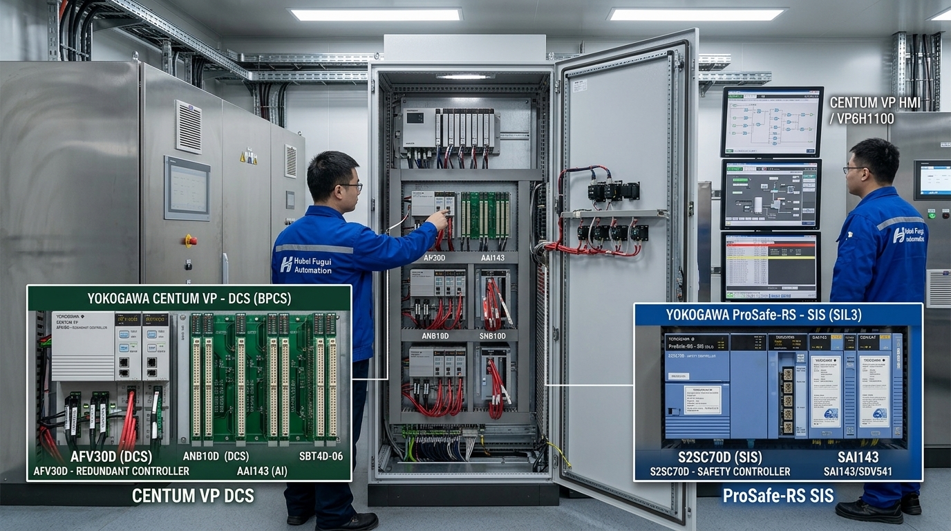
Never substitute DCS hardware for Safety Instrumented Functions (SIFs) requiring Safety Integrity Level 2 (SIL2) or Safety Integrity Level 3 (SIL3). While CENTUM VP controller units (e.g., AFV30D) deliver high availability through pair-and-spare redundancy, only ProSafe-RS controllers (e.g., S2SC70D) possess certified self-diagnostics capable of executing safety logic under IEC 61508 / IEC 61511 mandates.
1. Fundamental Operational Paradigms: Control vs. Safety
To establish a selection baseline, automation engineers must evaluate the operational posture of each system under normal and fault conditions:
- CENTUM VP (Distributed Control System): Designed to keep process parameters within active operating envelopes. The priority is high availability and process continuity. If an I/O card or controller processor experiences a transient hardware fault, the DCS is engineered to fail-over seamlessly without tripping the plant.
- ProSafe-RS (Safety Instrumented System): Designed to monitor the process for hazardous deviations and drive the process to a predefined “safe state” (typically de-energize to trip) upon detecting abnormal limits or internal subsystem failures. The priority is fail-safe integrity and diagnostic coverage.
2. Hardware Architecture & Diagnostics
The architectural distinction between CENTUM VP and ProSafe-RS lies in the execution pipeline within the Central Processing Units (CPUs) and the I/O bus interface modules.
CENTUM VP Pair-and-Spare Architecture
The core field control unit of CENTUM VP (such as the AFV30D Dedicated Controller Unit) utilizes a Pair-and-Spare microprocessor arrangement. Each controller housing contains two processing cards, and each card integrates two MPU cores running identical software instructions in tight lock-step synchronization.
If a hardware disagreement occurs between the primary pair, control transfers instantly to the secondary pair within a fraction of a millisecond, preventing process disturbance. This design guarantees high operational uptime, but it is optimized for continuous control rather than SIL-rated safety shutoff verification.
ProSafe-RS Dual Electronic Architecture
In contrast, the ProSafe-RS Safety Control Unit (such as the S2SC70D Safety Controller Unit) implements a single-module, dual-processor arrangement certified up to SIL3 according to IEC 61508. The system executes dual redundant calculations while performing active background diagnostic checks on internal memory registers, field loop wiring integrity, and internal clock frequencies.
Hardware Comparison: Processor & I/O Module Architecture

CENTUM VP Controller: AFV30D-A41452 (24V DC) / AFV30D-A41252 (220V AC)
- Redundancy Model: Pair-and-Spare (High Availability Focus)
- Standard I/O Cards: AAI143 (16-Ch AI 4-20mA), AAI543 (16-Ch AO), ADV151 (32-Ch DI)

ProSafe-RS Controller: S2SC70D-SA14010 (24V DC) / S2SC70D-SA12010 (220V AC)
- Redundancy Model: Dual-Processor with Advanced Self-Diagnostics (Fail-Safe Focus)
- Safety I/O Cards: SAI143 (Safety AI), SAI533 (Safety AO), SDV144 (Safety DI), SDV541 (Safety DO)
3. Deep Comparison Matrix: CENTUM VP vs. ProSafe-RS
| Architecture Dimension | CENTUM VP DCS System | ProSafe-RS SIS System |
|---|---|---|
| Primary Application | Continuous Control, Regulatory Control, Batching, Data Logging | Emergency Shutdown (ESD), Fire & Gas (F&G), Burner Management (BMS) |
| Safety Certification | Basic Process Control System (BPCS) per IEC 61511 | TÜV Certified up to SIL3 (Single Controller) per IEC 61508 |
| Fail State Policy | Maintain operation via bumpfree redundant switchover | De-energize to trip / Fail-safe state upon unrecoverable error |
| Main Processing Units | AFV30D-A41452 / AFV30D-A41252 | S2SC70D-SA14010 / S2SC70D-SA12010 |
| I/O Expansion Nodes | ANB10D-445 / ANB10D-425 Terminal & Intermediate Nodes | SNB10D-445 / SNB10D-425 Safety Local Node Units |
| Bus Infrastructure | ESB Bus (ANT401 / ANT501, YCB301 Cables) | Safety ESB Bus (SNT401 / SNT501, SEC401 Cards) |
| Environmental Protection | Optional G3 Conformal Coating (/K4A00 /D5A00) | Standard Conformal Coating for harsh environments |
| Software Suite | VP6 Engineering Suite (VP6E51AD, VP6H1100 HMI) | ProSafe-RS Engineering Software / CENTUM Integrated HMI |
4. Engineering Co-Integration: “One Architecture” Concept
Historically, integrating a DCS from one vendor and a SIS from another required complex Modbus RS-485 interfaces, custom memory mapping, and separate operator consoles. Yokogawa eliminated this operational friction through seamless hardware and software co-integration.
Integrated Control and Safety System (ICSS)
ProSafe-RS connects directly to the same Vnet/IP control network utilized by CENTUM VP. Consequently, process alarms, safety interlock statuses, and diagnostic alerts from ProSafe-RS natively pass to the CENTUM VP Human Machine Interface (HMI) package (e.g., VP6H1100-V11N01) without requiring gateway programming.
- Unified Alarm Management: Process operators view DCS operational alarms and SIS safety trips on a single integrated alarm summary display, adhering to ISA-18.2 standards.
- Time Synchronization: Sequence of Events (SOE) recorders across both AFV30D control units and S2SC70D safety control units are synchronized to within 1 millisecond via Vnet/IP, enabling root-cause analysis following process trips.
- Consolidated Software Maintenance: System administrators manage maintenance contracts and software updates through standardized frameworks like the SV2CPML-V1103 (DCS Annual Maintenance) and SS2CPMLM-V1103 (SIS Annual Maintenance) licenses.
5. Module Selection & Hardware Bill of Materials (BOM) Guidelines
When engineering field control panels or expanding existing cabinet footprints (such as standard Rittal 800×800×2105 mm enclosures), specifying the correct combination of node units, cards, and cabling is vital.
DCS Analog & Digital Module Selection Rules
- Harsh Environment Protection: For chemical plants containing corrosive airborne gases (sulfur dioxide, hydrogen sulfide), specify modules with G3 Conformal Coating. Use part suffix extensions like AAI143-H50/K4A00 G3 or ADV151-P60/D5A00 G3.
- Signal Isolation: Ensure transmitter input loops employ 16-channel isolated cards (e.g., AAI143 for 4-20mA inputs and AAI543 for outputs) combined with Pepperl+Fuchs dedicated isolators (e.g., HIC2025 or HIC2031) or intrinsic safety barrier terminal boards (e.g., HICTB16-YC3-RRB-KS-CC-A016).
- Node Termination: When configuring remote expansion racks via ESB bus, place terminal node units (ANB10D-445-CU2T) at the end of the chain, while intermediate nodes (ANB10D-445-CU2N) link daisy-chained positions. Interconnect nodes using high-grade bus cables like YCB301-C100 or YCB301-C200.
SIS Safety Module Selection Rules
- Dedicated Safety I/O: Never wire trip signal inputs (e.g., High-High pressure switches, ESD pushbuttons) to standard DCS ADV151 or AAI143 cards. Use dedicated ProSafe-RS safety cards: SAI143-H63 for safety analog inputs, SDV144-S63 for safety digital inputs, and SDV541-S63 for safety digital outputs.
- Safety Relay Interfacing: Route high-power trip signals through dedicated safety relay output boards like the SRM540-000 or SBD4D-06 to maintain galvanically isolated fail-safe loops.
6. Procurement & Life-Cycle Spare Parts Planning
Unplanned plant downtime costs continuous process facilities tens of thousands of dollars per hour. Maintaining a strategic spare parts inventory mitigates long lead-time supply chain disruptions during turnarounds or emergency outages.
Recommended Critical Spares On-Site Inventory
For a standard 2,000-point ICSS system, maintain at least one hot-swappable processor spare (DCS: CP471-00 or CP461-50; SIS: S2CP471-01), two power supply units (DCS: PW484-50; SIS: SPW484-53), and a 10% inventory buffer of high-density I/O modules with pre-installed connection headers (e.g., SBT4D-06).